It’s Christmas time! Yeah! … Are you bored? Me too. Hearing the same Christmas songs every year all over again. Boring love movies on all channels and they aren’t even half good as they were before. So let’s make it more interesting. One thing I like about Christmas is that it lifts the spirits (when you are not bored to death by stupid music and bad movies). Another thing is the christmas lights everywhere. They blink, they glow, they do all kinds of weird and wonderful things. And it can become an obsession. The more you get involved into building the lights, the more pleasing it is to watch them. How about making a simple Christmas lights controller?
Ok. Let’s define our goals
- We need to make a controller that blinks LED lights in a non-boring way
- We can start with cheap lights from the shop – we don’t want to get even more bored when we solder hundreds of LEDs to a cable, right?
- We need at least 7 different blink patterns…
- … and a button to change patterns.
Good. What’s next.
Pick a microcontroller
I’ll try to keep it simple and pick a small, cheap MCU – let’s say PIC12F1501. It has 4 PWM channels, 3 of which we’ll use. And it’s easy to upgrade if you run out of memory or pins. If you do, you can easily switch to PIC16F1503, or PIC16F1508, or PIC16(L)F1509 and you don’t need to change much in code.
Build a prototype
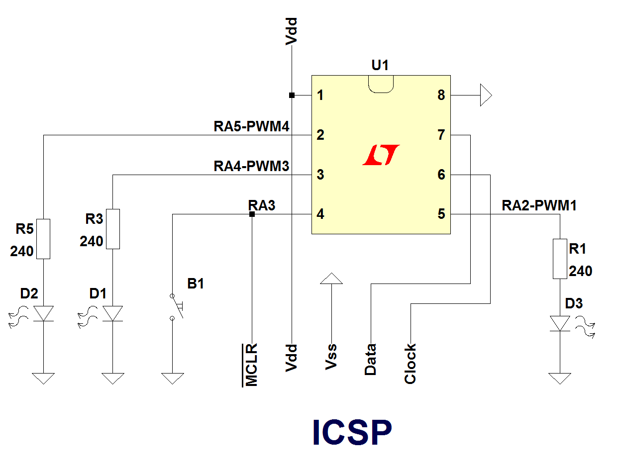
Let’s first try to make blink patterns with 3 leds instead of hundreds. Here is the basic schematic:
Then put it together on a breadbord:

Let’s test it by making the simplest possible code. If you build a circuit for a first it’s never a good thing to start with a complex firmware. So, something like this is a good start. The leds will blink and when you push the button they will light continuously. This way you test both LEDs and the button. Here is the code:
#define _XTAL_FREQ 16000000

#include <xc.h>

#pragma config CLKOUTEN = OFF
#pragma config WDTE = OFF // or control in software - SWDTEN
#pragma config PWRTE = OFF
#pragma config CP = OFF
#pragma config BOREN = OFF
#pragma config MCLRE = OFF
#pragma config FOSC = INTOSC

#pragma config STVREN = ON
#pragma config LPBOR = OFF
#pragma config BORV = LO
#pragma config LVP = OFF
#pragma config WRT = ALL // we don't need self write
void init(){

  // IO setup

  // RA2,RA4, RA5 - OUT - LED
  // RA3 - IN - button
  TRISA = 0x0B; // 0000 1011
  ANSELA = 0; // all pins are digital
  OPTION_REGbits.nWPUEN = 0; // enable weak pull-ups
  WPUA = 0x08; // pull up on RA3

}

void main(void){
  OSCCONbits.IRCF = 0xF; // 1111 = 16MHz
  OSCCONbits.SCS = 3; // internal clock
  init();
  while(1){
    if(PORTAbits.RA3){
      LATA = 0b000100; // RA2
      __delay_ms(200);
      LATA = 0b010000; // RA4
      __delay_ms(200);
      LATA = 0b100000; // RA5
      __delay_ms(200);
    }else{
      LATA = 0b110100; // RA5
    }
  }
}
Take it to the next level – PWM
If you really want nice Christmas lights then you better use PWM. What is PWM? Pulse width modulation is when you control the lenght of the pusles, while keeping the friquency the same. I will probably write an article, but meantime you can take the code as it is and experiment with it. When you push the button leds should slowly fade in. When you release it they will slowly fade out.
Let’s initialize the PWM module:
PR2 = 0x3F; // period

#define PWM_COM_SETUP (_PWM1CON_PWM1EN_MASK | _PWM1CON_PWM1OE_MASK \
        | _PWM1CON_PWM1OUT_MASK) & ~_PWM1CON_PWM1POL_MASK
//we are dong this for each PWMCON register:
// PWMxCONbits.PWMxPOL = 0;
// PWMxCONbits.PWMxOUT = 1;
// PWMxCONbits.PWMxOE = 1;
// PWMxCONbits.PWMxEN = 1;

  PWM1CON = PWM_COM_SETUP;
  PWM3CON = PWM_COM_SETUP;
  PWM4CON = PWM_COM_SETUP;

  T2CONbits.T2OUTPS = 0;
  T2CONbits.T2CKPS = 0;
  T2CONbits.TMR2ON = 1;
Microchip’s PWM module is a bit tricky when you look at it first time. For example when you set the period you set only the most significant 8 bits. When Timer 2 reaches PR2 value it restarts from 0 again. If you want 10 bit PWM then you should set PR2 to 255. But PR2=255 at system clock 16MHz means that the timer will overflow every (16 MHz / 4 = 4MHz divided by timer 2 ticks 256 – from 0 to 255) 15.625kHz It’s not too bad – you are probably not going to see the flicker, but it’s not very good either. A good frequency for LED pwm is 50-100kHz. The problem with using 8 bits is that it’s harder to set the pulse width value. Here is a function that will do just that:
typedef struct{
		unsigned short PWMDC;
		unsigned char PWMCON;
} pwmReg_t;
pwmReg_t pwmReg[3] @0x611;

void setPwm(unsigned char pwmCon, unsigned char pwmValue){
  union{
    struct{
      unsigned char B0;
      unsigned char B1;
    };
    unsigned short W;
  } word;
  word.B0 = 0;
  word.B1 = pwmValue;
  word.W >>= 2;

  pwmCon--;

  pwmReg[pwmCon].PWMDC = word.W;
}
To make the most efficient code we need to declare an array that points to PWM registers. Then to set pwm3 module pulse width to 100 you just call setPwm(3, 100);.
Get the full PWM test program in the links section at the bottom of this page.
Make them dance
Ok. Enough playing with microcontrollers! Let’s play with lights. I’ve written a program that blinks the leds in 7 different ways. It’s configurable, so you can change speed, pwm values or even replace some of the programs with your own if you don’t like it. You also have program zero which loops through all 7 program in specific time. Check for a link in the downloads section at the bottom of this page.
Configuration starts with config.h file:
PROGRAM_CHANGE_TIME is the time in seconds. you can choose a value between 1 and 255 seconds.
#define PROGRAM_CHANGE_TIME 10
PROGRAMx_MIN and PROGRAMx_MAX are the minimum and the maximum pulse width for each program. If you don’t want LEDs to switch off completely – increase mimum. If leds are too bright – decrease maximum.
#define PROGRAM1_MIN 0
#define PROGRAM1_MAX 128
Then you have programInit() function in each program.c file. In the beginning you have timer 1 setup.
This sets the postscaller I made for tiemr 0 which defines the speed of LED animations. Value is from 1 to 255 which sets post scaller from 1:1 (fastest) to 1:255 (slowest).
timer0PostScaller = 3;
This sets the time0 perscaller. The prescaller is hardware based and it’s set by the first five bits of OPTION_REG. Put any value between 0x00 (1:2) to 0x07 (1:256) or set to 0x08 to turn the prescaller off (1:1).
OPTION_REG &= 0xF0;
OPTION_REG |= 0x06;
Then in some programs you have starting values for PWM:
pwm1Value = PROGRAM1_MIN;
pwm3Value = PROGRAM1_MIN+(PROGRAM1_MAX-PROGRAM1_MIN)/3;
pwm4Value = PROGRAM1_MIN+(PROGRAM1_MAX-PROGRAM1_MIN)/3*2;
Starting values only make sense for programs that rotate the values. If you have patterns (like program 5 to 7) changing the starting value won’t affect the animation.
If you want to change code a bit more, for example by adding another program) you might want to switch to PIC16F1503 microcontroler because even though I did my best to make the program small it fills 943 of the available 1024 instructions. Switching to 16 bit patterns would make the program smaller.
Let’s see where are we:
Downloads
- firmware-running-light – a simple program to test your circuit
- firmware-pwm-test – a simple program to test PWM
- cl-firmware16 – Christmas lights firmware with 16 bit patterns (source code and HEX) – leaves you more ROM memory to write your own code
- cl-firmware32 – Christmas lights firmware with 32 bit patterns (source code and HEX)
- Schematic (PNG)
To be continued…
in the next part: connect long strip of leds to the christmas lights controller.