Everyone says that it’s bad to use loops for delays in microcontrollers. But why? It’s a lot easier to make it that way. In most cases there are macros available that’ll do the calculations for you and will make the correct loop to delay the precise time. Why would they do these macros if it’s bad to use them. Well it really depends on what you are doing. It’s not always bad. In this article I’ll show you the benefits of using interrupts and why/when it’s good to use them and when you should not to use them.
Delays using instruction cycles
Making a simple delay is not that hard. In part 2 of the “First steps with microcontrollers” tutorial I showed that you can do it with simple for loop. But how do you know what time it takes for one cycle of the loop? To answer that we must see the assembly code and check the datasheet.
Here is what an empty loop looks like in assembler when you compile it with Hi-tech C compiller. To view the assembly listing select “Disassembly listing” from View menu:
25: for(i=0;i<255;i++){ // wait a bit

7D2 01F1 CLRF 0x71
7D3 0871 MOVF 0x71, W
7D4 3AFF XORLW 0xff
7D5 1D03 BTFSS 0x3, 0x2
7D6 2FD8 GOTO 0x7d8
7D7 2FD9 GOTO 0x7d9
7D8 2FDB GOTO 0x7db
7D9 2FE5 GOTO 0x7e5
7DA 2FE5 GOTO 0x7e5
7DB 3001 MOVLW 0x1
7DC 00F0 MOVWF 0x70
7DD 0870 MOVF 0x70, W
7DE 07F1 ADDWF 0x71, F
7DF 0871 MOVF 0x71, W
7E0 3AFF XORLW 0xff
7E1 1D03 BTFSS 0x3, 0x2
7E2 2FE4 GOTO 0x7e4
7E3 2FE5 GOTO 0x7e5
7E4 2FDB GOTO 0x7db
26: // do nothing
27: }
Wow, that’s complex. That surprised even me. Why would they do that? It’s simple – money. They do it for money. I’m sure with no efforts it could be reduced to 4-5 instructions, but they make it bigger instead to make you purchase the full version. Well we’ll have to make our own delay to make it simple. Here it is a pretty simple code that does the same and … it’s free:
void simpleDelay(unsigned char i){
#asm
mySimpleLoop:
    dec     simpleDelay@i // decrease i by one
    btfss   03h, 2 // btfss STATUS, Z - skip if Zero flag is set
    goto    mySimpleLoop   // repeat
#endasm
}
Ok. Now let’s check datasheet, TABLE 15-2: PIC16F627A/628A/648A INSTRUCTION SET. We see that most instructions are 1 cycle. Exceptions are goto and test-skip instructions like btfss that we used. Goto is always 2 cycles and btfss is one cycle if condition is not met and 2 cycles otherwise. So let’s count:
dec      simpleDelay@i    - one cycle
btfss   03h, 2                   - one cycle most of the time and the last time it takes 2 cycles
goto    mySimpleLoop             - two cycles
Let’s take i=2 for example. on first pass we have 4 cycles and i will decrease to 1. second we have dec – one cycle, i becomes 0, so btfss will skip goto and it’s 2 cycles so 3 cycles total in second pass. The whole loop is 4 + 3 = 7 cycles. If we change the value for i you’ll see that we get i*4 – 1 cycles. And how long is one instruction cycle? The answer is on page 15 of the datasheet (FIGURE 3-2: CLOCK/INSTRUCTION CYCLE). You can see that every instructions cycle takes 4 clock cycles. But how long is one clock period. Clock period (T) depends on system frequency (F): F = 1/T and also T = 1/F.
So if F = 48kHz (or 48000 Hz) like the “First steps” tutorial then the time will be T=1/48000 seconds. that’s 0.0000208s or 0.0208 ms or 20.8 microseconds. That’s the clock period. Instruction cycle is 4 times longer – 4*20.8 = 83.2us. One loop is 4 cycles * 83.2 = 332.8 microseconds. so the total delay will be i*332.8 (you can ignore the fact that the last loop is 3 cycles instead of 4). If i = 100 that’s 33.28 ms or about 0.033 seconds. that’s not much. if can be maximum of 255 because it’s unsigned char or one byte which is 84.864 ms. You’ll ask how do you get bigger delays. Well you could put one NOP (no operation) instruction after DEC. This way you get one more instruction and total period of 5 instruction cycles in the loop. That’s 416ms per loop cycle or maximum of 0,106s so if you want one second delay you must call the function 10 times.
It sounds complex and it is. But there is a way to cheat. As I mentioned before there is a useful tool in MPLAB ide – the StopWatch (under Debugger menu). It gives you the exact time and number of instructions. You can zero the StopWatch at the start of the function while debugging and check what it’s showing at the end. You can do that even for the complex For loops. And there is even easier way – some compilers will contain a delay function and/or macro in their library. With Hi-Tech C and XC8 you can use _delay, __delay_ms or __delay_us macros and the compiler will do the calculations for you. Of course you’ll have to define _XTAL_FREQ:
#define _XTAL_FREQ 4000000 // in Hertz. put this before any includes
.....
__delay_ms(100); // delay 100 ms
Delays using interrupts
You probably heard that using instruction cycles for delays is bad. Well it’s not bad, but it’s not suitable in some situations. Often you want to do multiple tasks with the microcontroller. Let’s say you want to do a clock for example. You want to blink a led ever half a second, increase the seconds every second and display the time on a display of some kind. doing all these things take different time, so your delay won’t be precise. For example if you increase seconds it takes one cycle, but you have to check if seconds are greater than 59 and then zero the seconds and increase the minutes. So every minute you have additional work to do which will add to your delays. The proper way is to use system timers in combination with interrupts.
What is a system timer? It is a simple counter that counts pulses. Some timers can have different pulse sources. One pulse sourse is the internal system oscillator or the clock cycle depending on implementation. Usually it’s the instruction cycle. But that’s not the only source. You can have an external source (connected to a pin on the MCU) – like pressing a button or a realtime clock chip. Some microcontrollers have secondary oscillator which is meant for lower frequency like the famous 32768Hz. That’s what frequency is used to make real time clocks … mostly. Why 32768Hz? It’s exactly 2^15. It would be nicer if we had 65536Hz crystals because that’s the counts of 16 bit timers in MCUs. So 16 bit timer will overflow every 2 seconds if driven by 32.768kHz.
Ok. Enough talking let’s see it in practice. Let’s build a timer that can be set to delay precise amount of seconds. Because internal oscillator is not precise enough we’ll use quartz crystal setup. For more information check 14.2 Oscillator Configurations section in the datasheet. And to make it more interesting we’ll make the timer to turn a relay for specific time and then turn it off. The relay can be used to control more powerful appliances like your TV, a light bulb or anything that’s within the relay maximum current rating.
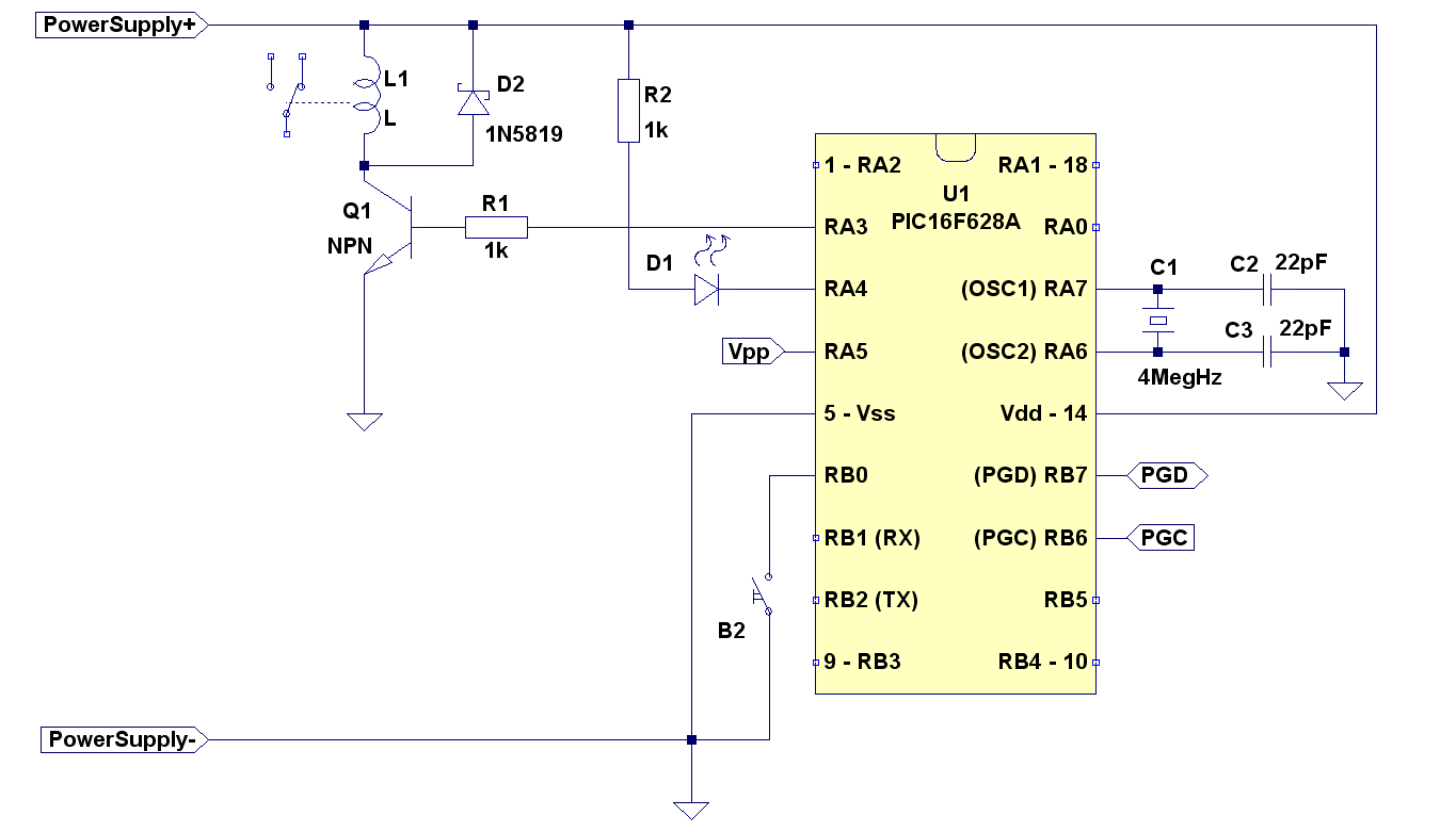
RA3 will be used to control the relay. We need a transistor to control the relay because most relays require more than maximum current rating of a pin (20 mA). You can use any general purpose transistor like 2N2222A for example. Most general purpose transistors can stand at least 100mA collector current and most relays require less than 100mA. RA4 will drive the led. You wander why I didn’t swap them to look more beautiful (the lines will not cross). Well pin RA4 is differen from the others. I had a lot of troubles with it because I didn’t check the datasheet. It’s an open drain configuration and it only connects to ground when it’s bit is set to zero. It doesn’t connect to Vdd when the corresponding bit is set to one because there is no second transistor on it. Why did they decide to spare that transistor? I dont’ know. Maybe it would be too complex to have it and it would increase the price with one or two cents. Just keep it in mind when designing circuits. And yes, I know I could have used RA2 for the led. I just wanted to point out the difference of pin RA4 on this particular controller. You can of course use RA2 (pin 1) if you want.
If you haven’t worked with a quartz crystal it may look scarry, but it’s not. It’s just a component and it’s not that expensive. The button we connect to RB0 because it has what’s called “an edge interrupt”. It’ll interrupt only when button is pressed and not when it’s unpressed. But in order the button to work you need a pull up resistor (in this case). The pull-up resistor is actually inside the MCU (check the datasheet) and it can be activated or deactivated by software. The diode D2 protects the transistor from voltage spikes coming from the relay coil when it’s switched on or off. It doesn’t have to be a schottky diode. You can use any rectifier diode – like the famous inexpensive 1N4007. Remember to always put a diode on coils and relays and don’t mess the direction – cathode to positive, anode to negative. If you turn it around it’ll act as a short on your power supply.
Now that we designed the circuit let’s write the program. We said that the instruction cycle is 4 times less than system clock – that’s 1MHz. Round number!!! Well it’s not that round when the timer counts to 65536 (from 0 to 65535). So how do we convert that to seconds? We have to make it count to round number. A way to do that (with this particular MCU) is to set the timer to a specific value so it doesn’t start from zero. If we want to make it interrupt every 50 000 cycles, then it must start from 65536-50000 = 15536. Easy! Or is it? Here is our interrupt:
void interrupt interruptHandler(void){
  if (PIR1bits.TMR1IF ) { // did timer 1 interrupt occur?
    PIR1bits.TMR1IF = 0;
    //add 15536 as it has started from 15536
    TMR1L = TMR1L + 0xB0; // 15536 = 3CB0 in hex, 3C is the high byte, B0 is the low.
                          // and we want to do TMR1L first before it's overflowed
    TMR1H = TMR1H + 0x3C;
  }
}
In order for an interrupt to occur we need to initialize the proper registers as well as set timer 1 into correct mode:
  // external interrupt configuration
  OPTION_REGbits.nRBPU = 0; // enable port b pull-ups
  OPTION_REGbits.INTEDG = 0; // interrupt on falling edge of RB0
  INTCONbits.INTE = 1; // enable external interrupt

  // timer 1 setup
  T1CONbits.T1OSCEN = 0; // we won't use the oscillator we'll use:
  T1CONbits.TMR1CS = 0; // T1 will use internal instruction cycle clock (Fosc/4)
  T1CONbits.T1CKPS = 0; // pre-scale 1:2
  TMR1H = 0x3C;
  TMR1L = 0xAF; // 15536 = 3CB0 in hex, 3C is the high byte, B0 is the low.

  INTCONbits.PEIE = 1; // enable peripheral interrupts (for timer1 int)
  PIE1bits.TMR1IE = 1; // enalbe timer 1 interrupt
  INTCONbits.GIE = 1; //enable interrupts

  // ready ?
  T1CONbits.TMR1ON = 1; // Go ... starts the timer.
Let’s try that. Choose MPLab simulator debugger (see First steps tutorial part 3 ). Put a breakpoint in the first line of the interrupt. Set the processor frequency to 4GHz (in debugger settings) and open the StopWatch. Now pres F9 2 times to ignore first interrupt. Zero the StopWatch and press F9 again. The stop watch shows 50 003 us. What? We either made a mistake in calculations or there is something mysterious going on here. Let’s check the disassembly code:
9:                     TMR1L = TMR1L + 0xB0; // 15536 = 3CB0 in hex, 3C is the high byte, B0 is the low.
   036    080E     MOVF 0xe, W
   037    3EB0     ADDLW 0xb0
   038    008E     MOVWF 0xe
Well that explains part of the problem. In address 036 the compiler decided to read the value of TMR1L into WREG. Then add 0xB0 while TMR1L actually increases, then store the value which is already 2 cycles old back in TMR1L. A solution would be if we do that in one instruction maybe it’ll work:
void interrupt interruptHandler(void){
  if (PIR1bits.TMR1IF ) { // did timer 1 interrupt occur?
    #asm
      movlw 0xB0
      addwf _TMR1L // add B0 in one instruction
    #endasm
    TMR1H = TMR1H + 0x3C; // we know that TMR1H won't change so we don't have to do it in assembly
  }
}
Try that in MPLAB and … fail! It’s 50 001. The timer stayed one cycle longer than it should. And this is your first real world practice lesson: Not everything is going according to the plan :). Yes, even professionals miss simple things when they design it and it doesn’t work when they run the circuit for the first time. Well that’s not that big of a problem if you find out what was the problem. And here the problem is the way the microcontroller executes the instructions. It first reads the value, then increases it and puts it back to the register. And somewhere in between timer 1 increases. So you have to compensate for this one single increase that you missed. For more information on read-modify-write check 5.3 I/O Programming Considerations section in the datasheet.
So what do you do? it’s simple – just add one to compensate the timer increase you missed:
void interrupt interruptHandler(void){
  if (PIR1bits.TMR1IF ) { // did timer 1 interrupt occur?
    #asm
      movlw 0xB1
      addwf _TMR1L // add B0 in one instruction
    #endasm
    TMR1H = TMR1H + 0x3C; // we know that TMR1H won't change so we don't have to do it in assembly
  }
}
And bingo – every interrupt occurs exactly 50.000ms after the previous one. It would be nicer if we had interrupt every 0.1 seconds. we could use the timer pre-scale setting. But then timer increase will happen every second instruction. So you don’t know if you have to compensate or not. If you happen to make to addition when timer is not increasing then you don’t have to compensate. So the solution could be to just use 20 interrupts per second (50ms) or check with debugger if you have to compensate and then never change the code before the addition. Well you better have timer1 interrupt processed first anyway, because you don’t want the register TMR1L to overflow. But things can change even if you don’t change the code, but change project settings – like C compiller optimisation. Compillers can be nasty sometimes. You could also do postscalling in software:
volatile union {
  struct {
    unsigned timer1pass :1; // define one bit
    unsigned reserved   :7;
  };
} flags;
volatile unsigned char sec10;
volatile unsigned int sec;

void interrupt interruptHandler(void){
  if (PIR1bits.TMR1IF ) { // did timer 1 interrupt occur?
    PIR1bits.TMR1IF = 0;
    // add 0xb1 to TMR1L
    #asm
      movlw     0xb1
      addwf     _TMR1L
    #endasm
    TMR1H = TMR1H + 0x3C;
    if(flags.timer1pass){ // second time
      sec10++;
      if (sec10>=10){
        sec10 = 1;
        if(sec > 0){
          sec--;
        }
      }
    }
    flags.timer1pass = ~flags.timer1pass; // toggle the flag
  }
  // process other interrupt sources here, if required
}
You can test it by putting a breakpoint on line that increases sec10 (the 10th of a second). Every time you press F9 the StopWatch will increase with exactly 0.100000 seconds. You probably noticed that I also added seconds countdown “sec” which will decrease untill it reaches zero. That’s what we’ll use for our countdown.
The main program would look like this:
void main(void){
  init();

  while(1){ // repeat forever
    if(sec == 0){
      PORTAbits.RA3 = 0; // turn the relay off
    }else{
      PORTAbits.RA3 = 1; // turn the relay on
    }
  } //while
}
Simple!!! Now the only thing left is to turn set the cowntdown to a specific value when you press the button. We’ll do that in the interrupt function:
void interrupt tc_int(void){
  // ... here is the timer1 interrupt handing. I skipped it for clarity

  if (INTCONbits.INTF) { // did external interrupt occur?
    INTCONbits.INTF = 0;
    sec = 60; // 60 seconds = 1 minute. you can set this up to 65535
              // seconds which is more than 18 hours, or even make it long int
              // which could be set to more than 136 years.
  }

  // process other interrupt sources here, if required
}
and the initialization of the external interrupt is like this:
OPTION_REGbits.nPBPU = 0; // enable port B pull-ups
INTCONbits.INTE = 1; // enable external interrupt
Now comes the scary moment when you have to build the circuit and see if it works. Let’s be brave and do that:
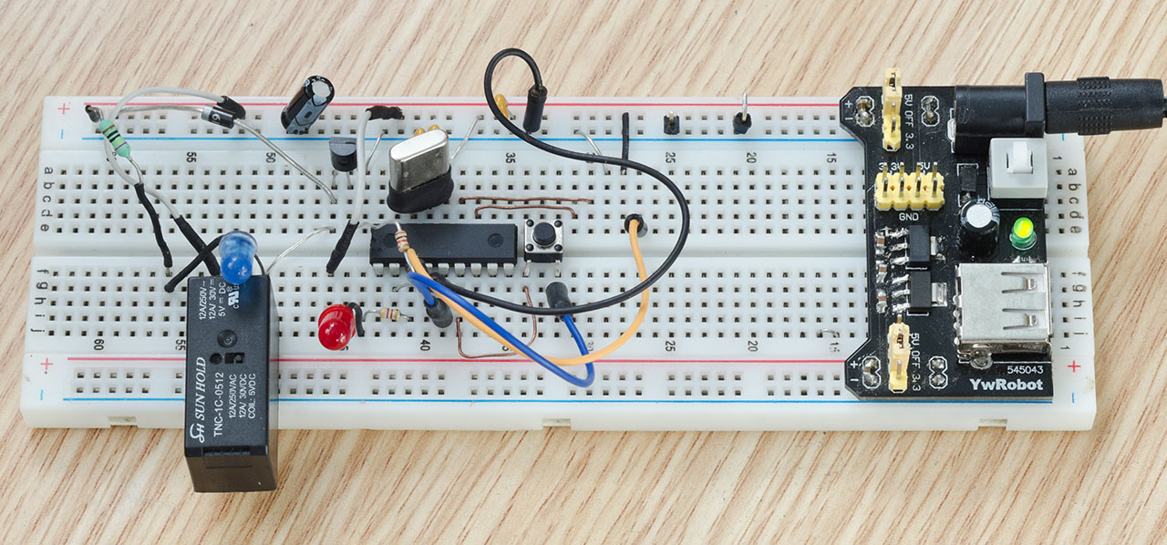
Well, it didn’t work. I messed up few pins, but I checked everything, fixed mistakes and now it’s running:
You’ll notice I’ve added few more things to the source code.
Source code
countdown.zip – Hi-Tech C code. The compiled .hex file is included (countdown.hex) so you can program it directly to your PIC without having to install IDE, however you will be stuck to the 5 seconds timer. It might be a good idea to use the hex file and ensure that it’s working before you tweak the code.