(running the first program)
When you write programs for devices it’s a lot worse when something goes wrong. For example if you output the wrong signal, depending on your schematic you might be making a short circuit. Or if you are trying to run a LED with PWM you might make it run constantly and the current could be too much. That’s why it’s better to run the program in simulator before running it on the MCU.
In MPLab you can use few different debuggers. To choose MPLab Simulator as a debugger select “Debugger->Select Tool->MPLAB SIM” from the menu. Now that you have selected a tool more options appear in MPLab.
When debugging you might want to turn on few tools. Stopwatch is the one that we need now – “Debugger->Stopwatch”. I also turn on “View->1 Memory Usage Gauge” and “View->Watch”.
Before running the program you might want to set breakpoints. To put a break point double click on a row (yes I’m used to double click to select a word, but now I can’t) or right click->Set Breaklpoint. You need breakpoints on RA0=1; and RA0=0; lines (in main(), not init() ) in order to check the time between blinks. And the last, but not east is to setup the simulator Processor Frequency so the time measurements can be accurate. Choose “Debugger->Settings …” from menu and in the “OSC / Trace” tab write 48 in “Processor Frequency” input and select units “KHz” on the right. Now you are ready to go. Press F9 to run the program. If you have set your break point correctly it should stop on the RA0 = 1; line:
![]()
Now Stopwatch is showing that about 583 microseconds have passed (they use the letter “u” instead of μ). Click on “zero” button to zero the timer and press F9 to run again. Now it should have stopped on the next breakpoint:
![]()
Look at the stopwatch now. It’s showing about 234 mSec (miliseconds). That’s about a quarter of a second. Run again to see the full period – it’s about 469ms – about half a second. So your LED will blink twice a second. It is actually possible to calculate this time based on how many instructions have passed, but sometimes it’s better to just use the timer. Plus it’s really a bad idea to use empty for loop for generating delays. The idea was to make the first program as simple as possible. We’ll see later how to use timers and interrupts to create delays.
Ok. Now what? Let’s run that on the real MCU! First you need the schematic:
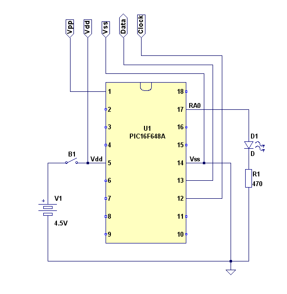
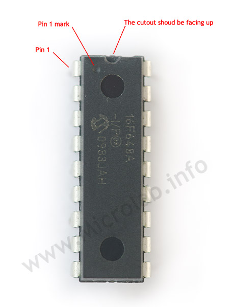
This particular MCU works from 3 to 5V so you can power it of 3 1.5V batteries. Make sure you don’t reverse the polarity. (+) goes to 5 and (-) to 14. The cut on the top of the IC shows where the first pin should be located:
For a schematic this simple you can’t go wrong with a breadboard. Actually always use breadboard to do “the blink test”. What could go wrong is to reverse the LED. So you better test if you connected the LED correctly. Make sure you disconnect posdf from MCU and connect LED as it should be connected – Anode to Pin 17, Cathode to 470 ohm resistor and the other end of the resistor to ground. Then connect Battery (+) to the LED:
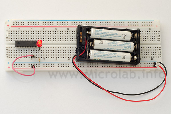
If it doesn’t light – reverse it. Usually the longer wire is anode. Keep in mind that LEDs can only take certain amount of voltage in reverse direction or certain amount of current in forward direction. This means that if you use the right resistor you can power a led from higher voltage, but if the LED is connected the wrong way it’ll burn. Most LEDs can withstand 5 volts in reverse, so you should be safe.
Now that we know the LED is connected the right way we can continue and build the full schematic:
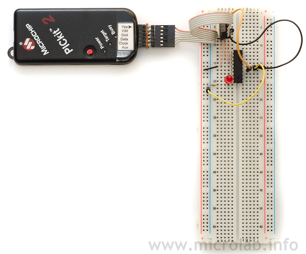
Let’s program the MCU. First connect the PICKit2 to the microcontroller. Download and install PICKit2 utility if you haven’t already, and run it. Select MCU family – “Menu->Device Family->Midrage->Standard” Choose “File->Import Hex” and select your hex file (blink.hex) from the project directory. Now click on the “write” button. If you’ve done everything correctly the program will be written into the MCU. To test it at first you can use PICKit2 to power the circuit. Check the “On” checkbox and the diode should start blinking. Now remove the PICKit2 and plug the batteries. It blinks!!!
Some people will say why would you go through all these troubles to blink a LED while you can buy blinking LED for few cents. I said it many times and you’ll probably get tired of me repeating it, but: “start with simple things and do one step at a time”. For every new MCU I study I first do the blinking test to make sure I connected everything correctly. There are some devices that need a lot more than +and – from the power supply to turn on – like short leads filter caps, a capacitor on the regulator pin, connect all all the power pins, an quarz crystal and more.
Files:
1. Program1.zip – full project source code