In part 1 we made 3 leds blink in different patterns. In this part we’ll connect to string of LEDs to make it look more like Christmas lights.
Choosing proper LED lights
The first thing to do is choose what kind of LED lights we can control. We can’t control lights that are directly connected to 220V. Well technically we can control it with triac, but once switched on triacs can’t switch off until there is no current flowing in the output circuit. This event happens only when the AC voltage passes zero point – 100 times per second for 50Hz power lines and 120 for 60Hz ones. The old types of christmas lights use that feature to control the lights using triacs, but the flicker is visible sometimes, especially if they control leds and not regular bulbs. But how do you know which one will work. Well simply look at the controller box. If it sais anythign between 3 and 33 volts it’s ok. You can also get christmas lights without controller which are continuously powered on. Make sure these have a transformer and check the voltage that it outputs less than 33 volts. You can also use battery powered christmas lights.
What’s not going to work
Here are some photos of lights that you don’t want to connect to this controller:
 Lights directly connected to power line |
 Controller connected directly to power line |
Anything that connects directly to power line (110/220V) – not good.
What is going to work
Everything that’s powered by voltage lower tan 33 volts will do the job:
 Battery powered lights |
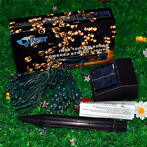 Solar powered lights |
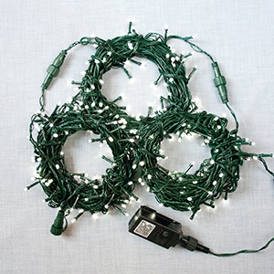 Lights with transformer |
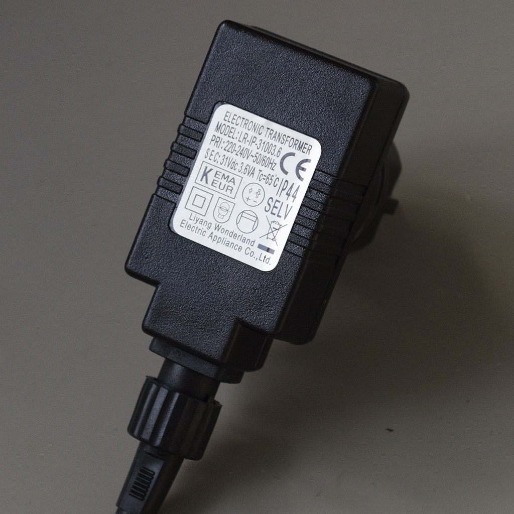 Transformer |
You can also buy a three single color led strips or RGB (reg-green-blue) led strip like these:
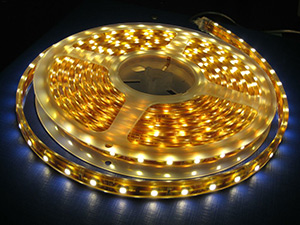 3x single color led strip |
 RGB led strip |
Schematic
In order to control more leds we need some kind of buffer. One reason is because PIC output pins can not source or sink more than 20 mA. Another reason is that most LED lights are connected in series therefore powered by higher voltages – like 12V, 24V or 30V. We can use either a MOSFET or a BJT transistor. It’s much cheaper to use B JT so I’ll use it. Also most MOS transistors have lower breakthrough voltage. If your strip is powered by 30V it might be a bit difficult to find MOS transistor for that voltage.
We also have to power the microcontroller. We can’t directly power it form 30V. The simplest way is to use 78L05 or 7805 regulator. it only needs few milliamperes, so 78L05 is enough:

If you are using battery powered LEDs, the voltage regulator is not required. Also you might need to use MOSFET transistors because BJT have relatively big voltage drop. So if your christmas lights are powered by 2×1.5V batteries, then use MOS transistors. Just keep in mind that some mos transistors have relatively high DS resistance and will drop more than BJT. Also some MOS transistors require higher voltage on Gate to switch on. Make sure to choose one that’s 2V or less (batteries don’t always stay at full voltage).
If they are powered by 3×1.5V then using BJT is probably ok. You have to test it. Here is the circuit for battery powered devices:

And if you don’ t want to buy bathetteries you can use your PC’s USB port by putting a diode serially on the positive supply. The voltage drop on the diode is about 0.5V. Any rectifier diode would be fine – like 1N4004/1N4007.
Keep in mind that battery powered lights have the LEDs connected parallely. This means that there is usually current limiting resistor. Some chinese might rely on the internal battery resistance and the fact that the LED voltage is pretty close to the battery voltage. In order to verify if there is a resistor (if you don’t see it or can’t trace it) you can turn the lights on and measure battery voltage and then voltage directly on LEDs. If they are the same there is no resistor. Check this link for current limiting resistor calculation.
If power supply is 20-30V they can get away without using current limiting because 10 LEDs in series have quite bigger range of working voltage. Let’s assume that a LED has somewhere between 3.0 and 3.1 volts when the current is 10mA. If it’s 3.0 and you power it from 3.2 the current will be twice higher and the other way around. But if you put 10 leds in series they will be happy anywhere between 30 and 31 volts. Of course there is nothing better than proper constant current driver.
Choosing a transistor
If you don’t have exactly the same transistor you can use any other switching transistor, but you have to follow these rules:
- The maximum collector current (Ic) must be more than what LEDs consume. Make sure it’s at least 10-20% more.
- The collector-emiter (Vce) breakdown voltage must be 2-4 volts less than the power supply. The more the better.
- Take DC current transfer ratio (hFE) into account. Base current = (Vdd-Vbe)/Rbase multiplied by minimum value of hFE must be at least 20% less than collector current.
If the hFE thing is too complex for you just pick a transistor that has minimum hFE about 50 at the current your LEDs draw. In the datasheet there is usually values for different collector current values.
Series Resistor
The LEDs I found were connected in groups of 10 by 10 LEDs in series directly to 31 volts. I used only 9 groups divided to 3 groups by 3 channels. There is no current limiting resistor or current source. However I decided to add series resistor of 68 Ohms, but I was too lazy to put one resistor for each LED group and I’ve put a resistor to each channel. If your LED lights don’t have a resistor I would recommend to put one to each group like in the schematic above. The value you can find by testing. Measure the current without a resistor and then experiment with different values to make the current drop not more than 10-20%. This will reduce the chance of LEDs burning from surges.
Preparing the LEDs
First things is to measure the LEDs supply voltage. Cut the wire near the power supply like this to prevent short circuit:

Measure the voltage of the power supply with and without LEDs connected. If the difference (voltage w/o LEDs – voltage with LEDs) is more than one volt, the power supply is constant current type. If it’s less than 0.5V – it’s constant voltage. If it’s between 0.5V and 1V probably no one knows the type of this power supply. For this application it doesn’t matter what type the power supply is. How ever you might have some problems with constant current power supplies.
Usually the LEDs are connected groups like the ones I described above. The idea is to achieve something like this:
If your LEDs don’t have a controller you might have to carefully unsolder LED groups (because they are soldered all together) and split them to 3 channels.
Building the circuit
Like any other circuit, you better build this one step by step and test it along the way:
- First solder the 7805 voltage regulator. Connect power supply to input and measure the output. Attention!!! Make sure input capacitor is rated for 35 volts and make sure you connect power to the input, not the output.
- Solder the output diode which will protect the regulator from damage when programming the MCU.
- Solder the microcontroller and the ICSP header. Connect a programmer and check if it’s programming correctly.
- Connect LEDs like in part 1.
- Program the MCU and connect power supply to check if LEDs are working.
- Solder the output transistors.
- Connect LED strips. You can start with one channel, then test it and add more.
- Power it on. If it doesn’t work – check troubleshooting section.
Troubleshooting
First problem that even I experienced is to mess up the voltage regulator connections. Double check the chip pinout. Make sure you’ve put input capacitor rated for at least 35 volts. Every time you have a problem measure the regulator output first.
If you can’t detect the chip with your programmer try these things:
- Check ICSP header connections.
- If you are trying to connect anything other than a button to RA3/MCLR – remove it before programming.
- Remove the C4 capacitor. If it works without it – try choosing lower value or use a jumper to temporarily remove it while programming.
- Depending on how powerful your leds are, the hFE (DC current gain) of your transistors you might need to lower the base resistors’ value. Don’t use value under 1k because the regulator might become quite hot. Use heatsink if you use resistors under 10k.
Links
- cl-firmware-array – Updated version of the firmware. Patterns use array of bytes instead of 32 bit integer.